🚀 Elevate Your Projects with the Ultimate ESP32 Experience!
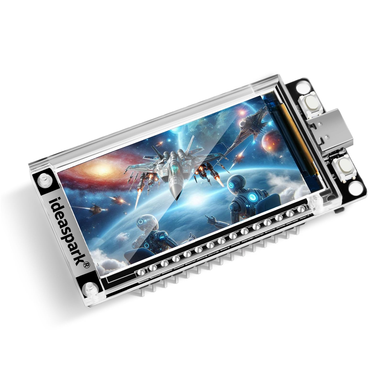
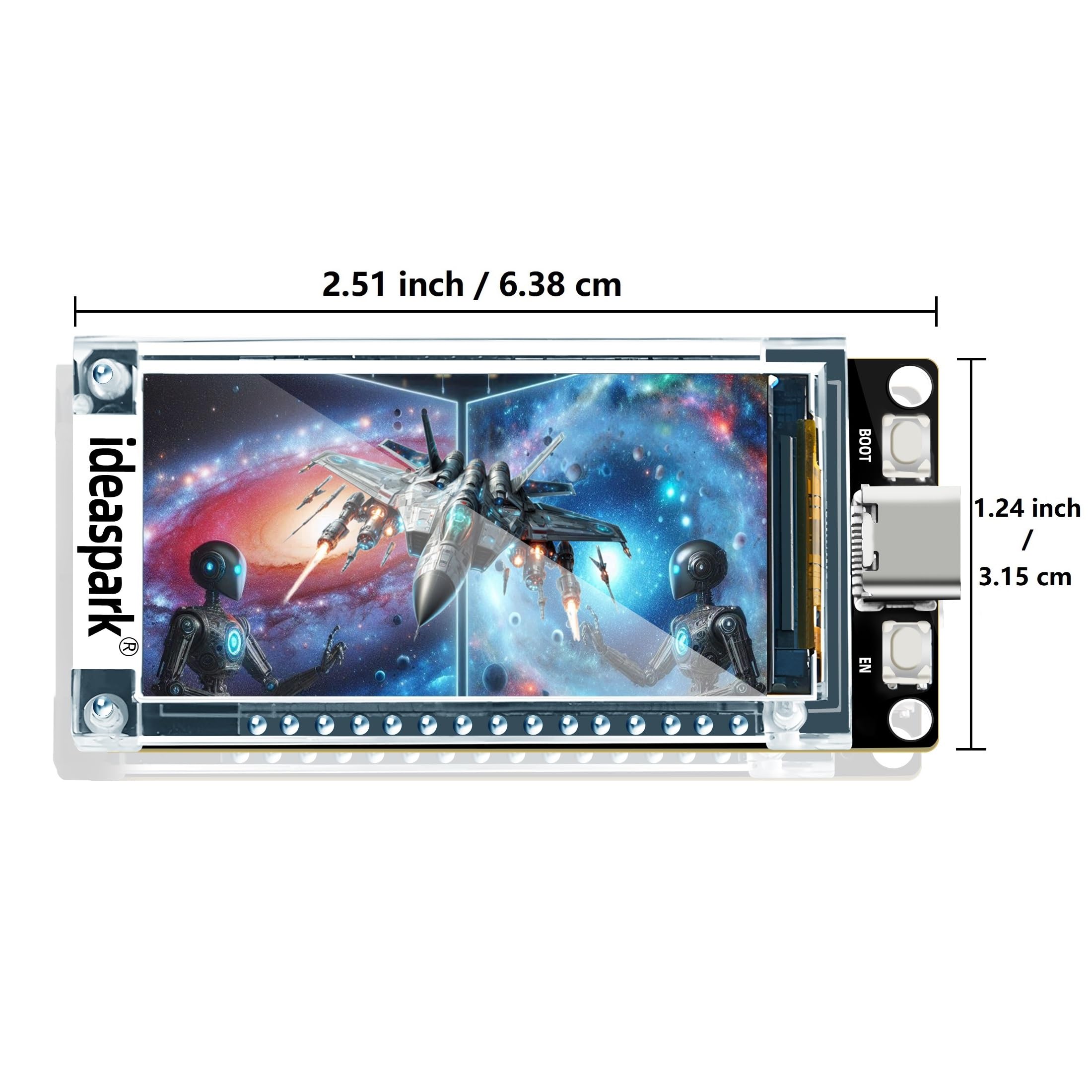
The ESP32 Development Board features a 1.9-inch ST7789 TFT LCD display with a resolution of 170x320, integrated Wi-Fi and BLE capabilities, and 16MB of flash memory. Designed for seamless integration and minimal setup, this board is perfect for a variety of IoT applications, making it a must-have for tech enthusiasts and professionals alike.
| Wireless Type | 802.11ac |
| Brand | ideaspark |
| Series | ESP32 Development Board |
| Item model number | ESP32 1.9 inch LCD(Solder PIN) |
| Item Weight | 1.13 ounces |
| Product Dimensions | 2.83 x 2.05 x 0.63 inches |
| Item Dimensions LxWxH | 2.83 x 2.05 x 0.63 inches |
| Processor Brand | Espressif |
| Number of Processors | 1 |
| Manufacturer | ideaspark |
| ASIN | B0D6QXC813 |
| Country of Origin | USA |
| Date First Available | June 11, 2024 |
S**R
Interesting ESP32 breadboarding possibilities
I bought a couple of these and had only the usual difficulty plugging the module into a standard solderless breadboard. Getting all 30 pins inserted into a breadboard, particularly a new one, takes patience, but the pin spacing is correct so this is no worse than any other ESP32.The module is wide enough that to make connections to the GPIO pins it's easiest to combine two breadboards, side by side (see photo). I've gotten the display working with the Adafruit TFT libraries and look forward to using the display for viewing real time trace messages of what's going on inside the ESP32. This should be a big help in debugging and, with 16MB of flash, there will be room for lots and lots of code.Or, maybe, have a couple of these around the house to show real-time status of the home security system I'm going to build. Someday soon ....
M**A
USB A=>C required.
Make sure you use USB A-C for the cable. Awesome integrated tool.
J**L
Soldering Quality is Terrible, Missing Battery Charger & Voltage Booster
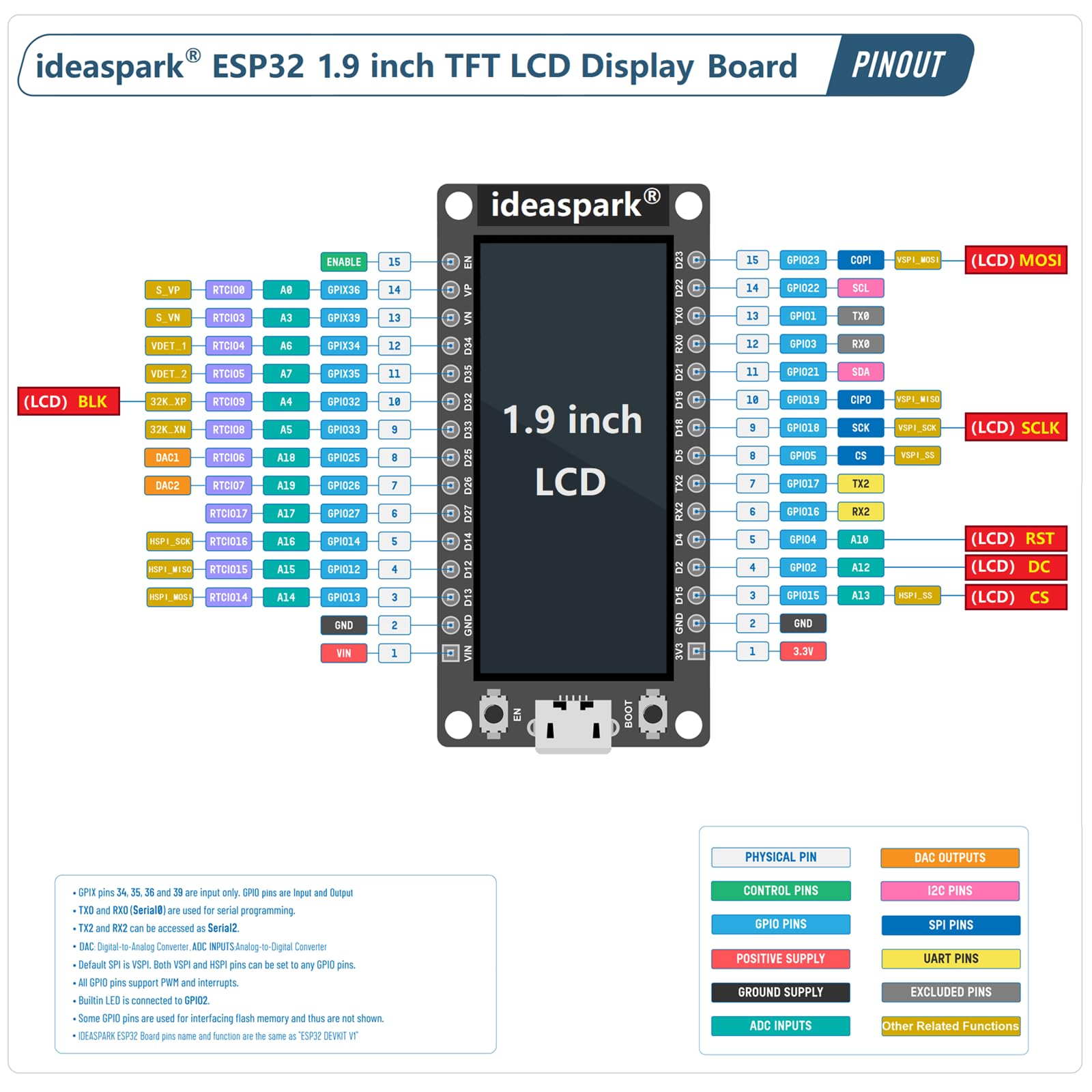
My brother purchased one of these boards, but had problems with it, because most of the components were not soldered. Out of curiosity, I purchased one as well. Mine booted as expected. I followed the instructions in the product images, and changed the image to my own image. I loaded the original factory program. All of the basic functions worked.However, my first real test was to attach a BME280 sensor and display the readings on the screen. I have used this sensor before, so I know it works. Wired the sensor to the default I2C pins (SDA: GPIO21, SCL: GPIO22) and could not get the sensor to work. When I removed the code for the display, which should be using SPI, the sensor worked without issue. I changed the I2C pins (SDA: GPIO12, SCL: GPIO14) and now the display and sensor work without issue. Since SPI and I2C are completely different, it didn't make sense that changing I2C pins allowed me to use both protocols. Looking at the pinout shows the default I2C pins are adjacent to the SPI pins used for the display. I checked continuity between the pins and found that GPIO22 and GPIO23 are connected. I looked at the solder joint, and they are indeed connected. Using a very small solder tip, I was able to fix the solder joint without removing the screen. I spent two evenings troubleshooting this board, but it works now...I think. Who knows what other solder issues I will find.---UPDATE---If the board has a boost module and/or battery charge circuit, they do not work. The screen operates at a much different brightness when on battery (3.7V) versus USB (5V). Battery connected to module does not charge when also connected to USB. So far (Jan 2025), I have yet to hear from the seller/manufacturer regarding specific board questions. Also, I have yet to find circuit diagrams. For these reasons, I am dropping my review to a single star.
A**R
If they made some improvements it would be a great board
The ESP32 Generic image from Micropython works but doesn't support the display. For the display, you need to build Micropython with russhughes/st7789_mpy on GitHub. There are prebuilt images there, but they are a little out of date. You then need to make a new tft_config.py file with the right pins and dimensions. You also need to modify the Micropython config if you want to take advantage of the full 16MB of flash.The board works, but it has some annoyances.- There's a blue LED on the DC pin for the display. You can turn it off, but it will turn on again every time you update the display- The pin rows are spaced 1.1 inches apart. Most ESP32 breakout boards are either 0.9 inches or 1.0 inches. I tried to contact the manufacturer to see if they could recommend a breakout board, but they didn't respond. 1.1 is also the width of a standard breadboard section, so you either have to span it across two breadboard sections or run some jumpers under the board.- The USB-C interface doesn't work with actual USB-C, so you have to switch from USB-C to USB-A and then back to USB-C to connectIt was fun to play with, but I'll probably look for something else in the future.
K**R
Fun in small package!
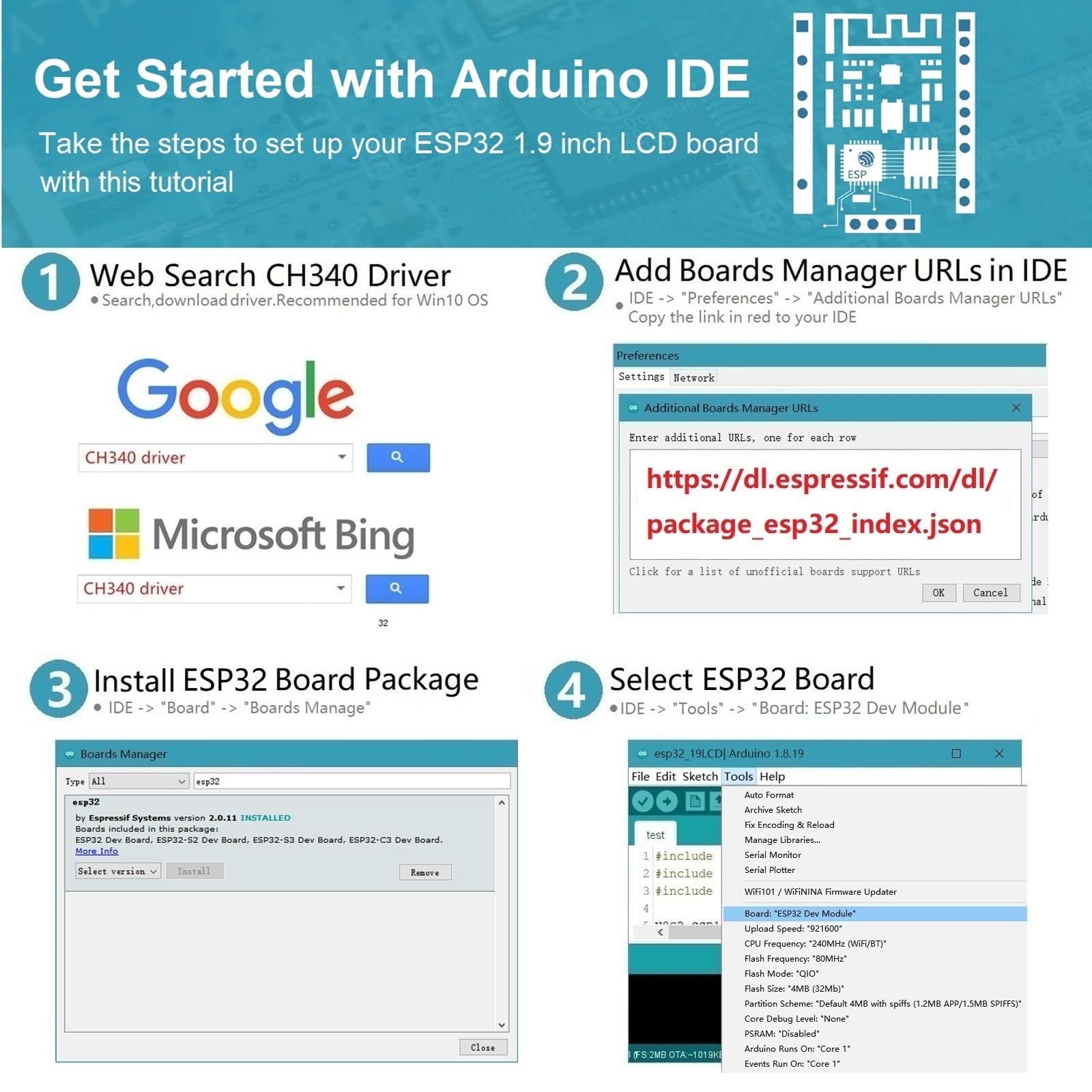
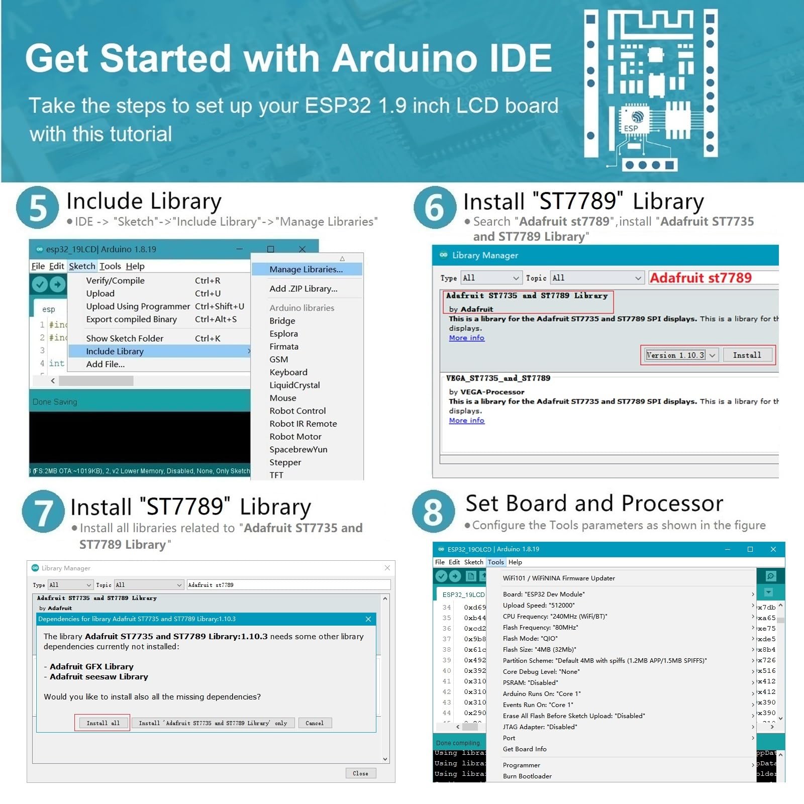
Wide capability in a easy to use package. Fast and reliable. Good display. Easy to program using the Arduino IDE. Compact enough to fit into all sorts of fun projects.Easy to make a stand-alone monitor for anything connected to the WiFi system. Or an NTS controlled clock. Or...
E**L
Wonderful product
The media could not be loaded. I was able to shrink a project of mine down considerable. I was using a full size ESP32 board and a separate 320x240 TFT display. But by using this module and the GUIslice library with GUIslice Builder along with TFT_eSPI graphic library in the Arduino IDE. I was able to make the enclosure much smaller.
S**N
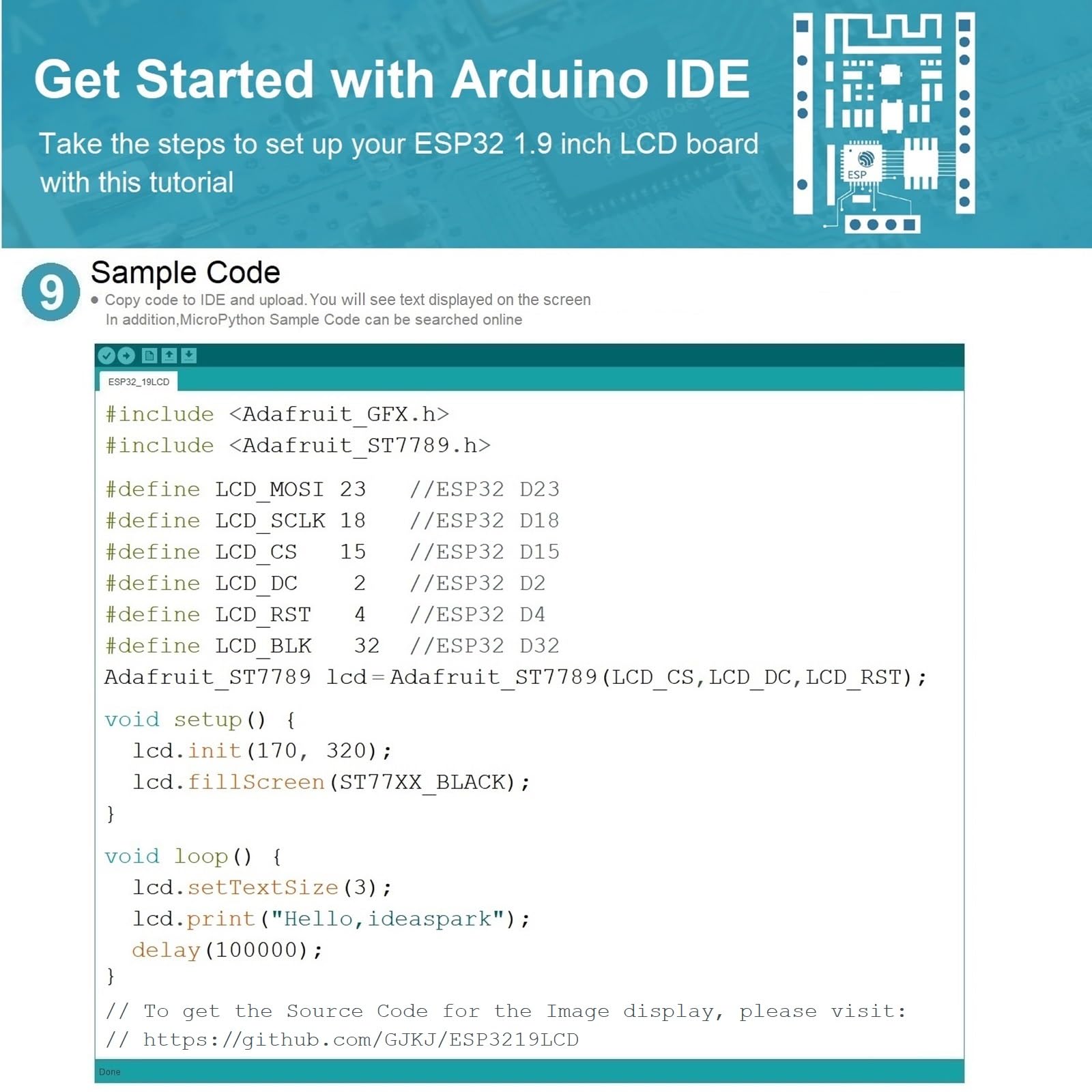
How to upload images to the esp32 board
There is no information on how to upload images to the LCD screen mounted on the esp32 board.i cannot find any programs on the Internet either.
Trustpilot
1 day ago
2 weeks ago