📻 Build it. Own it. Hear the difference.
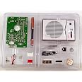
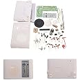
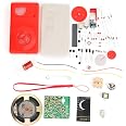
The TECSUN 2P3 AM Radio Receiver Kit is a premium DIY project designed for enthusiasts seeking superior AM reception and hands-on learning. With higher sensitivity than most AM radios, a portable battery-powered setup, and a complete radio case, it combines educational value with stylish portability.
| Item Weight | 1 Pounds |
| Item Dimensions L x W x H | 11"L x 8"W x 3"H |
| Style | Fun Radio Kit |
| Color | Multicolor |
| Hardware Interface | 3.5mm Audio |
| Frequency | 108 MHz |
| Speaker Maximum Output Power | 120 Watts |
| Power Source | Battery Powered |
| Tuner Type | AM |
J**S
This is the best AM radio kit available today
This is the best AM radio kit available today. Packaging, component quality, PCB quality, and final performance of the radio are all excellent. The radio is of moderate to moderate-high difficulty and is best performed by a builder with good soldering skills. A teen with prior experience assembling an electronic kit is ideal. Younger ages can assemble this kit with some adult assistance. Radio reception is very good for all local stations during the day and distant stations at night. Tuning is crowded due to the small size of the tuning knob and the density of stations on the AM band but that is typical of most small AM receivers.The assembly instructions are the most important part of any electronics kit and my personal opinion is the instructions rate 3 out of 5. The instructions are excellent in comparison to other kits available but room for improvement exists. Below is the criterion I used to rate the assembly document:Clarity - 3 out of 5, The information in the assembly instructions could have been better organized.Technical - 3 out of 5, The circuit technical description contains an average quality description of a superheterodyne AM radio. Some minor English language translation issues exist,Step-By-Step Assembly - 0 out of 5. The greatest weakness of the assembly document is the lack of clear step-by-step instructions.Print Quality - 5 out of 5. The print quality of the instructions is excellent. Drawings and schematic diagrams are excellent.Testing and Troubleshooting - 2 out of 5. The documentation contains minimal testing and troubleshooting instructions.One oddity with the assembly is the process for checking the idle current in three places on the PCB, and then using larger or smaller value resistors to bring the idle current within the desired range. When the current is within the desired range, the builder must solder closed some very small jumper pads. The currents to be measured were in the micro-amp range which is very difficult for the typical low-cost DVM to measure. Instead of measuring current, I recommend the manufacturer switch to measuring the voltage on the collector or emitter resistors. That is much easier to do with a low cost DVM and does not require the use of jumper pads. I used the voltage measurement process with good results.The assembly instructions recommend building each radio function block and then testing each one when completed. However the instructions do not indicate which component should be installed. Below is the order I installed the radio components in order to accomplish the goals of the manufacturer:Audio AmplifierEJ1 - Earphone JackIC1 - Audio Amplifier ICC8 - Electrolytic CapacitorC9 - Polyester CapacitorC10 - Electrolytic CapacitorC11 - Electrolytic CapacitorC12 - Electrolytic CapacitorC13 - Electrolytic CapacitorR14 - ResistorR13 - ResistorR12 - ResistorVR - Variable Resistor (Follow instructions on soldering VR to small PCB, the solder small PCB to large PCB)Battery HolderTest Audio AmplifierInsert batteries. Plug dynamic headphones into EJ1. Touch soldered terminals of VR with your finger and listen for hum and noise. Remove batteries. If you heard noise, proceed to the Detector section below. If you did not hear noise while touching VR, double-check that all components above were installed correctly and all solder joints are good, then repeat the audio test.DetectorC14 - Electrolytic CapacitorC15 - Ceramic CapacitorC6 - Ceramic CapacitorC7 - Ceramic CapacitorD1 - Detector DiodeR11 - ResistorShield CoverTest DetectorNo tests. Proceed to the 2nd IF Amplifier section below.2nd IF AmplifierT3 - TransformerQ3 - TransistorR10 - ResistorR8 - ResistorR3 - ResistorD4 - DiodeD2 - DiodeD3 - DiodeTest 2nd IFPerform current check indicated in instructions or the alternative test procedure I recommend below:A. Solder the terminals of Jumper Pad C together (Jumper Pad C is indicated in the top PCB layout of Figure 6 in the instruction document).B. Install the batteries and measure the voltage across R10 with a volt meter.C. If the voltage is between 50mV (0.05V) and 100mV (0.1V), remove the batteries and proceed to the 1st IF Amplifier section below.D. If the voltage at R10 is lower than 50mV, remove the batteries then remove R8 from the PCB and replace with a lower value (120K) from the extra resistors supplied in the kit.E. If the voltage at R10 is higher than 100mV, remove the batteries then remove R8 from the PCB and replace with a higher value (220K) from the extra resistors supplied in the kit.F. Repeat B and C.1st IF AmplifierSFU - Ceramic FilterC5 - Ceramic CapacitorC4 - Electrolytic CapacitorQ2 - TransistorR7 - ResistorR6 - ResistorR5 - ResistorR9 - ResistorT2 - TransformerTest 1st IFPerform current check indicated in instructions or the alternative test procedure I recommend below:A. Solder the terminals of Jumper Pad B together (Jumper Pad B is indicated in the top PCB layout of Figure 6 in the instruction document).B. Install the batteries and measure the voltage across R6 with a volt meter.C. If the voltage is between 0.6V and 1.2V, remove the batteries and proceed to the Local Oscillator/Tuning section below.D. If the voltage at R6 is lower than 0.6V, remove the batteries then remove R5 from the PCB and replace with a lower value (10K) from the extra resistors supplied in the kit.E. If the voltage at R6 is higher than 1.2V, remove the batteries then remove R5 from the PCB and replace with a higher value (22K) from the extra resistors supplied in the kit.F. Repeat B and C.Local Oscillator/TuningC1 - Ceramic CapacitorC2 - Polyester CapacitorC3 - Ceramic CapacitorC16 - Electrolytic CapacitorT1 - TransformerR4 - ResistorR1 - ResistorR2 - ResistorQ1 - TransistorVC3/VC4 - Variable CapacitorL1/L2 - AntennaTest Local Oscillator/TuningPerform current check indicated in instructions or the alternative test procedure I recommend below:A. Solder the terminals of Jumper Pad A together (Jumper Pad A is indicated in the top PCB layout of Figure 6 in the instruction document).B. Install the batteries and measure the voltage across R2 with a volt meter.C. If the voltage is between 0.5V and 1.0V, remove the batteries and proceed to the Local Oscillator/Tuning section below.D. If the voltage at R2 is lower than 0.5V, remove the batteries then remove R1 from the PCB and replace with a lower value (100K) from the extra resistors supplied in the kit.E. If the voltage at R2 is higher than 1.0V, remove the batteries then remove R1 from the PCB and replace with a higher value (150K) from the extra resistors supplied in the kit.F. Repeat B and C.Refer to the Figure 7 of the instructions for the following:Install the knobs, L1/L2 antenna mount, and back cover hex standoff.Secure the L1/L2 antenna with two wire ties supplied in the kit.Install the grill cloth and speaker in the speaker grill.Screw the speaker grill to the front case half.Solder the speaker to the PCB.Insert the PCB into the front case half and secure with screws.Insert the front knob faceplate onto the front case half.Insert batteries and power on the radio. You should be able to receive stations and hear them on the speaker and headphones.Install the back cover.Overall this is an excellent AM radio kit. The assembly instructions and testing sections could be better, but they are actually better than most other kits available today.
J**S
Great little radio with a couple little issues.
This radio is a kit so, if course, you must put it together. This means soldering all the components to the board, which requires some soldering skills. The directions are adequate but could certainly be better. They do Not give you a blow by blow step quide for each component as you would see in a Heathkit or Elenco. However, if you have even basic common sense and a bit of electronics knowledge, you really shouldn't have that much trouble building it. There are a couple quarks with it though. One is there are 3 test points that have a cut in a trace so after it's assembled, you are to test current at these points. If they are in range, in theory, you should be able to bridge the gap to close it. I found it was necessary to add a tiny bit of a discarded lead to bridge these points. One of them is in a pretty tight spot. The other thing is that the volume control works backwards. By this I mean when you first turn it on, what would normally be the lowest volume is the highest! That's pretty annoying. It was easily fixed, but it required a modification. I desoldered the 2 points for either side of the volume pot, and swapped the leads. It now works as expected.The circuit is a unique design in that with only 3 transistors, it's able to achieve quite a sensitive and selective radio! All of the actual receiver section is done with those 3 transistors! Yet it does have 2 IF stages. The audio amp is done with a single IC. The volume is quite good, and everything matches up well. The alignment is quite simple. It helps to have another radio to compare with so you know what station you are actually listening to. The finished radio is quite small and very usable. If course not many people are into a radio that is only AM now a days but I found it to be a fun experience and I do still listen to AM. Part of the reason it's as selective as it is, is due to the fact it uses a ceramic filter between the 2 IF stages. It has quite a large farrite bar antenna for such a small radio. Don't let the minor issues deter you from building this kit. I had a lot of fun doing it and got a good radio to boot so it was well worth the cost. I just wish they had designed it so the volume worked as normal. That is the reason I gave it 4 instead of 5 stars.
Trustpilot
1 day ago
2 weeks ago