🔌 Power Smartly, Live Freely!
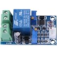
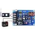
The 12V Battery Charging Controller Protection Board Module is an essential tool for anyone looking to safeguard their battery's health. This module automatically disconnects the load when voltage drops below a preset level and reconnects it when the voltage rises, ensuring optimal battery performance. With adjustable settings and a user-friendly LED indicator, this module is perfect for both hobbyists and professionals.


N**3
Very simple, great way to control loads on a solar install
You must add some non-conductive standoffs and mount on something. Works as advertised. It's a great deal for off grid solar where you want to run something (fridge or dehumidifier) while you are away, but do not want to drain the battery. All the entry level inverters I've worked with stop sourcing AC when the battery gets down to 10.5V. Way to low... kills the battery. So with this, you can set the voltage to what you want.. in my case 12V, or about 50% charge. Feed the output to a DC controlled AC relay (switch shuts off AC power if the DC voltage goes away).
R**Y
Works as stated
Bought 7 of them to protect the back up battery in remote devices. They all work just fine. Be aware that they do not come adjusted to any reasonable threshold levels. 5 of them you had to have a battery voltage of over 15 volts before they would turn on. DO NOT EXPECT THESE TO BE PLUG AND PLAY! I used a variable power supply and a good Fluke meter to set them to my liking. I don't see how you would adjust them any other way.
K**.
Works like it should
It does exactly what it describes. The "on" setpoint sets the voltage the relay turns on, the "off" setpoint sets the voltage it turns off at. It draws about 5mA when the relay is off, about 35mA when on. Adjustable power supply makes it much easier to set up.
C**Z
Very difficult to adjust
This unit is very difficult to get adjusted. I used two multimeters, soldered probe leads to the potentiometer pins so I could simultaneously monitor the reference voltages, and used my adjustable DC power supply, and it still took me like a half hour to get it adjusted into the range I wanted.It was NOT adjusted into any usable range as-delivered. It was delivered with a trigger voltage of like 4V,which is so low the LED comes on but the relay doesn't even click. The relay itself comes on about 9V and turns off about 3V.The printing on the PCB seems to refer to the switching voltage, not the reference voltage, which is OK. If you turn the potentiometers in the "+" direction, you will be reducing the reference voltage, but you will be increasing the voltage that it switches at. Confused yet?It's very easy to accidentally get the potentiometers adjusted "across each other" so that the unit does not work at all. What you want to do is get the "OFF" potentiometer adjusted to switch at a somewhat lower voltage than the "ON" potentiometer, so that when the unit turns off, it does not oscillate. It's easy to get the potentiometers adjusted by mistake so that the unit never turns off, never turns on, appears to be dead etc., and this is made worse by the cheapest potentiometers that respond poorly to the screwdriver. Also, if you have the unit hooked up to use its own battery voltage, which seems the most likely use-case, the reference voltages themselves change as the battery voltage goes up and down, making it even harder to figure out what's going on. The unit did eventually work, even when running of its own battery voltage, but this makes it even more complicated to setup. In the end these are the values I got, for protecting lithium 3-cell batteries:Switch-off battery voltage: 9.8VSwitch-off potentiometer Reference voltage: 0.9949 *when measured at 12.0V*Switch-on battery voltage: 10.4VSwitch-on potentiometer Reference voltage: 0.902 *when measured at 12.0V*Three stars because it didn't work out of the box, had no good instructions and was maddening to adjust.
B**Y
No idea what I'm doing
No instructions with this unit - it's just the board, in a static bag. The terminals are labeled on the PCB, but the pots aren't. Q&A here at Amazon state the startup switch is "mandatory", but that the unit should turn back on when voltage rises above a threshold.Haven't played with the pots yet - have it hooked up to a solar fountain with a small battery bank. Unit won't turn on unless I hit the "Mandatory switch". Unit then runs until it hits low voltage threshold though. I'm wondering if I can adjust one of the pots to get it to turn on without the switch - that was the impression I was given when I bought it... if I have to hit the button every time to start it, then it isn't terribly useful.Would be really nice if the pots where labeled at the least. Even better would have been a small bit of documentation. But I guess you get what you pay for.*Edit*The PCB is marked for the pots. While trying to adjust - unit sparked, won't turn off (always on when battery voltage is applied), but no voltage out output terminals. Lasted a grand total of 36 hours, never was able to get it working right.
S**R
While I like seeing the voltage I'm planning to put the is ...
I'm using this in my vehicle to disconnect power to my fridge while camping if the battery voltage drops too low. I went with this unit instead of others on Amazon for a few reasons.1) The disconnect and reconnect voltages are adjusted by the two potentiometers on the board. Most others have dip switches that force you to use a set of predetermined disconnect and reconnect voltages. Others had no adjustment at all.2) No voltage display. While I like seeing the voltage I'm planning to put this unit behind my lower kick panel where my wires from the fridge come into the fuse box. So no real reason for the display. That and that display uses more power which will create a larger drain on the battery when the engine is off for no real reason.3) This unit has an override capability. If you connect the two pins on the board inside the white connector it will override the disconnect/reconnect logic and connect the load. Could be useful for some. I haven't decided if I will use it or not since I don't see a situation where I would want to continue depleting the battery below my disconnect voltage. The type of connector needed is in one of the description photos. I ended up ordering one from digikey.Next step is to protect the circuit board from grounding out on anything behind the kick panel. I'm debating getting a small plastic enclosure, but I haven't found any that seem like a good fit. The unit is actually very compact. I may just spray a heavy urethane coating on it, and call it good.
Trustpilot
1 month ago
1 week ago